
As you've already learned, the results of a Modal Analysis load case are displayed in the program after a successful calculation. You can thus immediately see the first mode shape graphically or as an animation. You can also easily adjust the representation of the mode shape standardization. Do that directly in the Results navigator, where you have one of four options for the visualization of the mode shapes available for the selection:
- Scaling the value of the mode shape vector uj to 1 (considers the translation components only)
- Selecting the maximum translational component of the eigenvector and setting it to 1
- Considering the entire eigenvector (including the rotation components), selecting the maximum, and setting it to 1
- Setting the modal mass mi for each mode shape to 1 kg
You can find a detailed explanation of the mode shape standardization in the OnlineManual here.
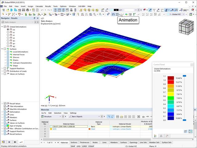
The deformation process of the global deformation components can be represented as a movement sequence.

- The steel connections model and the results can be saved as a separate model file
- The resulting stresses and the results of the stability analysis (joint buckling) can be displayed in a separate model
- In the saved model, you can run a deformation animation on the connection
- Connection components are converted to surfaces and members when they are saved

- Automatic consideration of masses from self-weight
- Direct import of masses from load cases or load combinations
- Optional definition of additional masses (nodal, linear, or surface masses, as well as inertia masses) directly in the load cases
- Optional neglect of masses (for example, mass of foundations)
- Combination of masses in different load cases and load combinations
- Preset combination coefficients for various standards (EC 8, SIA 261, ASCE 7,...)
- Optional import of initial states (for example, to consider prestress and imperfection)
- Structure Modification
- Consideration of failed supports or members/surfaces/solids
- Definition of several modal analyses (for example, to analyze different masses or stiffness modifications)
- Selection of mass matrix type (diagonal matrix, consistent matrix, unit matrix), including user-defined specification of translational and rotational degrees of freedom
- Methods for determining the number of mode shapes (user-defined, automatic - to reach effective modal mass factors, automatic - to reach the maximum natural frequency - only available in RSTAB)
- Determination of mode shapes and masses in nodes or FE mesh points
- Results of eigenvalue, angular frequency, natural frequency, and period
- Output of modal masses, effective modal masses, modal mass factors, and participation factors
- Masses in mesh points displayed in tables and graphics
- Visualization and animation of mode shapes
- Various scaling options for mode shapes
- Documentation of numerical and graphical results in printout report

- 3D incompressible wind flow analysis with OpenFOAM® software package
- Direct model import from RFEM or RSTAB including neighboring and terrain models (3DS, IFC, STEP files)
- Model design via STL or VTP files independent of RFEM or RSTAB
- Simple model changes using Drag and Drop and graphical adjustment assistance
- Automatic corrections of the model topology with shrink wrap networks
- Option to add objects from the environment (buildings, terrain ...)
- Wind load determined over the height of the building, depending on standard-specific parameters (velocity, turbulence intensity)
- K-epsilon and K-omega turbulence models
- Automatic mesh generation adjusted to the selected depth of detail
- Parallel calculation with optimal utilization of the capacity of multicore computers
- Results in just minutes for low-resolution simulations (up to 1 million cells)
- Results within a few hours for simulations with medium/high resolution (1‑10 million cells)
- Graphical display of results on the Clipper/Slicer planes (scalar and vector fields)
- Graphical display of streamlines
- Streamline animation (optional video creation)
- Definition of point and line probes
- Display of aerodynamic pressure coefficients
- Graphical display of turbulence properties in the wind field
- Optional meshing using the boundary layer option for the area near the model surface
- Consideration of rough model surfaces possible
- Optional use of a seond-order numerical Order
- Multilingual user interface (for example, German, English, Spanish, French)
- Documentation possible in the RFEM and RSTAB printout report
- Automatic consideration of masses from self-weight
- Direct import of masses from load cases or load combinations
- Optional definition of additional masses (nodal, linear, surface masses, as well as inertia masses)
- Combination of masses in different mass cases and mass combinations
- Preset combination coefficients according to EC 8
- Optional import of normal force distributions (in order to consider prestress, for example)
- Stiffness modification (for example, deactivated members or stiffnesses can be imported from RF-/CONCRETE)
- Consideration of failed supports or members
- Definition of several natural vibration cases (for example, to analyze different masses or stiffness modifications)
- Results of eigenvalue, angular frequency, natural frequency, and period
- Determination of mode shapes and masses in nodes or FE mesh points
- Results of modal masses, effective modal masses, and modal mass factors
- Visualization and animation of mode shapes
- Various scaling options for mode shapes
- Documentation of numerical and graphical results in the printout report
- For the design according to Eurocode 3, the following National Annexes are available:
-
 DIN EN 1993-1-5/NA:2010-12 (Germany)
 -
 SFS EN 1993-1-5/NA:2006 (Finland)
 -
 NBN EN 1993-1-5/NA:2011-03 (Belgium)
 -
 UNI EN 1993-1-5/NA:2011-02 (Italy)
 -
 NEN EN 1993-1-5/NA:2011-04 (Netherlands)
 -
 NS EN 1993-1-5/NA:2009-06 (Norway)
 -
 CSN EN 1993-1-5/NA:2008-07 (Czech Republic)
 -
 CYS EN 1993-1-5/NA:2009-03 (Cyprus)
-
- In addition to the National Annexes listed above, you can also define a specific NA, applying user-defined limit values and parameters.
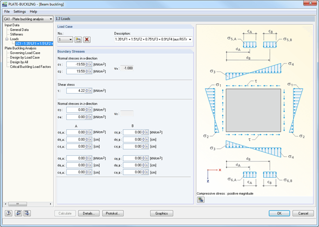
- Import of all relevant internal forces from RFEM/RSTAB by selecting numbers of members and buckling panels with determination of governing boundary stresses
- Summary of stresses in load cases with determination of governing load
- Different materials for stiffener and plate possible
- Import of stiffeners from an extensive library (flat plate and bulb flat steel, angle, T-section, channel, and trapezoidal sheeting)
- Determination of effective widths according to EN 1993-1-5 (Table 4.1 or 4.2) or DIN 18800, Part 3, Eq. (4)
- Optional calculation of critical buckling stresses according to analytical formulas of annexes A.1, A.2, and A.3 of EC 3, or by means of FEA calculation
- Designs (stress, deformation, torsional buckling) of longitudinal and transverse stiffeners
- Optional consideration of buckling effects according to DIN 18800, Part 3, Eq. (13)
- Photo-realistic representation (3D rendering) of buckling panel, including stiffeners, stress conditions, and buckling modes with animation
- Documentation of all input data and results in a verifiable printout report
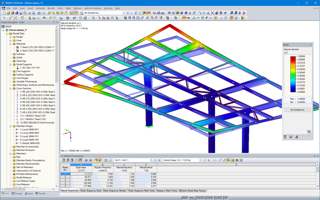
After the calculation, the eigenvalues, natural frequencies, and natural periods are listed. These result windows are integrated in the main program RFEM/RSTAB. The mode shapes of the structure are included in tables and can be displayed graphically or as an animation.
All result tables and graphics are part of the RFEM/RSTAB printout report. This way, clearly arranged documentation is ensured. Furthermore, it is possible to export the tables to MS Excel.
The results are displayed with references to EN 1993-1-5 or DIN 18800. In addition, RF-/PLATE-BUCKLING shows calculation results separately for the action of only one edge load as well as for the simultaneous effect of all edge loads.
In the case of several load cases, the governing load case is displayed separately. Thus, time-consuming comparison of calculation data is not necessary.
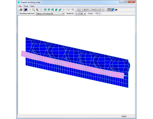
Window 2.5 lists the critical buckling load factors of all load cases and the respective buckling modes.
You can visualize the buckling modes and loads of the buckling panel in the graphic window. This facilitates a quick overview of the buckling modes and loads. Using the animation option, you can clearly represent the buckling behavior of stiffened plates.
Finally, it is possible to export all tables to MS Excel or in a CSV file.